Choosing between wired M-Bus and RS485 decides more than which two wires land on the terminal. It decides how the meter is powered, how it is addressed, how the data is defined, which gateways it can talk to, how the site is commissioned, and who maintains it ten years from now.
Short answer: if the project has to fit an existing EN 13757 / OMS head-end, or the meter has no battery and must be powered over the bus, wired M-Bus is usually the shorter path. If the site already runs a PLC, BMS or RS485 concentrator and you are prepared to define the register map, RS485 with Modbus RTU or CJ/T 188 is more flexible. The comparison is not about which interface is more modern — they assume different systems.
This article stays on selection and interface boundaries. The electrical derivation for M-Bus (1 UL = 1.5 mA, up to 250 slaves per segment, roughly 150 mA for 100 meters, master supply sized in the 500 mA class) is already worked through in our M-Bus retrofit guide; here we use the conclusions and move on to the decision.
| Item | Wired M-Bus | RS485 |
|---|---|---|
| What the standard covers | A metering bus system: physical layer in EN 13757-2, metering data model in EN 13757-3, plus the OMS specification family in Europe | TIA/EIA-485 defines the physical layer only; Modbus, CJ/T 188 or a project protocol defines everything above it |
| Wiring | Two-wire bus; polarity-free connection is possible when the slave interface supports it | Differential A/B pair; termination, bias and polarity must be confirmed in the system design |
| Power | The master powers the slaves over the bus; available current is limited by unit loads, line drop and the master supply | Communication and device power are usually designed separately; the meter keeps its own battery or local supply |
| Addressing | Primary address (commonly 1–250) and secondary address (manufacturer, device, version) | Defined by the application layer; Modbus RTU uses 1–247, with 0 for broadcast |
| Data organisation | Built for metering records: volume, unit, status, alarms, historical values | Flexible, but register address, data type, byte order and exception responses all have to be agreed |
| Typical use | Water, gas, heat and electricity meters read by one master; European utility projects | Buildings, industrial sites, existing RS485 networks, customer-defined protocols |
| Node count | Up to 250 slaves per segment; more requires another segment or a repeater | 32 unit loads by standard; up to 256 with 1/8 UL transceivers, in practice limited by cable length and baud rate |
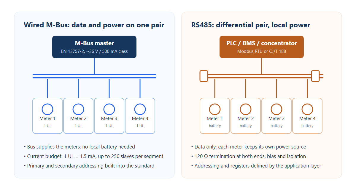
M-Bus grew out of meter reading: one master polls many meters for volume, reverse volume, alarms and status, and the bus solves the power problem at the same time. For meters installed in pits, expected to run for a decade without a battery change, and read directly by a utility head-end, that combination is hard to beat.
Four things decide whether it works in a given project:
RS485 is cheap, mature and everywhere. What it does not do is decide where a water meter's volume sits in a register map. That part has to come from Modbus, CJ/T 188 or the customer's own protocol, which means the real work in an RS485 project is not wiring — it is the interface document.
The cost of that flexibility is precision in the specification: device address range, baud rate and parity, register mapping including byte order and units, timeouts and retries, exception codes, and behaviour after a power cycle. Leave any of these open and commissioning turns into an open-ended loop.
This is the most common mistake in a selection meeting.
So "is RS485 better than M-Bus" is an incomplete question. Compare three layers separately: the physical interface, the application protocol, and the data model. Plenty of projects fail on the third layer after the first two appear to work — the bus is alive, but units or byte order do not match what the head-end expects.
Fill in the site conditions and the answer usually falls out. These are the six questions we ask first on a new project.
| Site condition | Lean | Reason |
|---|---|---|
| Existing EN 13757 / OMS head-end, or a European project | Wired M-Bus | Data model and addressing already exist on both sides |
| PLC, BMS or Modbus concentrator on site | RS485 + Modbus RTU | Joins the existing control network without a protocol gateway |
| No battery in the meter; bus must power it | Wired M-Bus | Two wires carry both communication and supply |
| Battery-powered meter, periodic reading only | Either | Decide on head-end compatibility, not on power |
| More than 200 nodes per segment, long cable runs | M-Bus (segmented) or RS485 segments | Both need a drop calculation; M-Bus plans around 250 per segment |
| Second-level polling or valve control | RS485 | Polling rhythm and real-time behaviour are easier to control |
| Shares a bus with heat or electricity meters | Wired M-Bus | Multi-utility buses are what the standard was designed for |
| Customer supplies a register map, no data model | RS485 | Implementation follows the table; the boundary is clear |
| Heavy interference, wet pits, frequent lightning | Either, with protection | M-Bus current loop is robust but still needs surge protection; RS485 needs isolation and TVS |
| Requirement for "connect either way round" | Check the slave first | Only true when the slave interface itself is polarity-free |
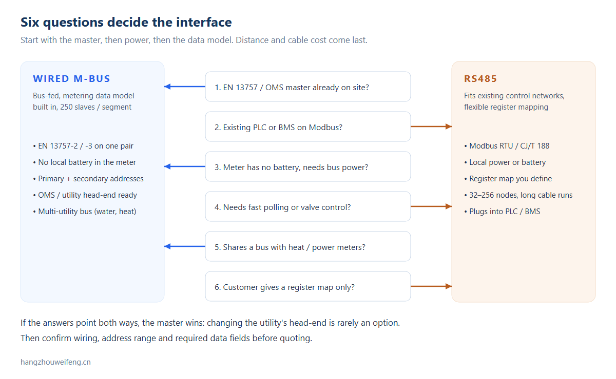
This table saves more time than any parameter table. A bus that "communicates" is not a working system.
| Interface | Symptom | Common cause | Check first |
|---|---|---|---|
| M-Bus | No slave on the segment answers | Bus short, master supply in protection, blown fuse | Measure bus voltage unloaded and loaded, then split the segment |
| M-Bus | One meter does not answer | Duplicate address, UL over budget, loose terminal | Read the primary address; total the UL and the drop to that point |
| M-Bus | Intermittent communication | Excessive line drop, contact resistance, undersized cable | Voltage at the farthest slave under load; crimp quality and oxidation |
| M-Bus | Communication works but data is wrong | Baud rate or parity mismatch, insufficient inter-frame gap | Compare parameters on both ends; check frame timing |
| RS485 | Nothing answers | A/B reversed, no termination, no bias so idle level floats | Measure differential level; confirm 120 Ω at both ends and bias |
| RS485 | One meter does not answer | Address conflict, different baud rate | Binary-search by powering meters off in groups |
| RS485 | High error rate on long cables | Missing termination, common-mode out of range, ground potential difference | Shielding and equipotential bonding; add isolated transceivers if needed |
| RS485 | Batch failures after a storm | No TVS or isolation; surge entered through the bus | Inspect protection devices and grounding, not just the transceiver |
One rule: measure levels before touching the protocol. When the physical layer is wrong, changing registers and baud rates only hides the problem deeper.
Getting a link to answer is not the same as passing the project. Validate all of the following, and write the result down:
A communication interface only matters if the metering data underneath it is stable. WF8002 detects the rotation of a conductive metal target inductively, without magnets, and supports forward/reverse recognition plus a standard pulse output. A WF8002-based metering PCBA then pairs with an M-Bus or RS485 communication module to turn mechanical motion into volume, reverse volume, alarms and status that the head-end can read.
For a new project we evaluate the sensing structure, the target path, installation space, power architecture, target protocol and head-end data requirements, and propose a matching sensor, stand-alone metering PCBA, or M-Bus / RS485 module combination.
No. Both serve metering communication and share similar data concepts, but one is a two-wire bus and the other is a radio link. A project cannot ignore RF planning, power and network deployment just because the data model looks familiar.
No. RS485 is the physical interface. Modbus is one application protocol that runs on it; CJ/T 188 or a customer protocol can run on the same wires.
Not always. The bus can power a slave, but whether a valve drive, backup supply or separate metering supply is needed depends on the meter architecture and the valve current.
Yes, when two conditions hold: the sensor can detect those states, and the protocol and head-end data model assign them a defined code or register.
The head-end data definition and full-meter validation. A link that answers does not prove that volume, reverse volume, alarms, power-cycle recovery and multi-node polling meet the project requirement.
They should not be mixed. The levels, power scheme and electrical structure are different (M-Bus is a current loop at roughly 36 V; RS485 is a differential pair), and combining them on one cable risks damaging interfaces. Where both must exist, use a dual-port concentrator or a protocol gateway with two separate segments.
EN 13757-2 allows up to 250 slaves per segment, but the practical limit is usually the unit-load total, the master supply and the drop at the farthest meter. Calculate current from UL first, then check voltage drop against cable gauge and length.
It depends on the master supply; there is no single number. Masters commonly specify around 36 V with a supply capability in the 500 mA class, but usable current must cover line losses and still leave the farthest slave above its minimum operating voltage. Size from the master datasheet and a site drop calculation.
32 unit loads by standard, or up to 256 with 1/8 UL transceivers. Real limits come from cable length, baud rate and termination. Modbus RTU addresses run from 1 to 247.
Send us the meter body or internal photos, the target movement, installation space, power conditions, target protocol, head-end requirements and expected volume. Our engineering team will evaluate the sensing, the metering PCBA and the M-Bus / RS485 module fit.
Products → | Technical documents → | Send an inquiry →
Email: Jing@hangzhouweifeng.cn
References: EN 13757-2 (wired M-Bus physical and link layer); EN 13757-3 (application layer and data model); Open Metering System specification; TIA/EIA-485-A; MODBUS over Serial Line Specification and Implementation Guide; CJ/T 188.
Related reading: M-Bus retrofit: three routes, wireless M-Bus water meter, NB-IoT AMI architecture.


