Ⅰ Summarize
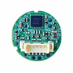
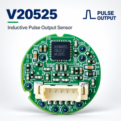
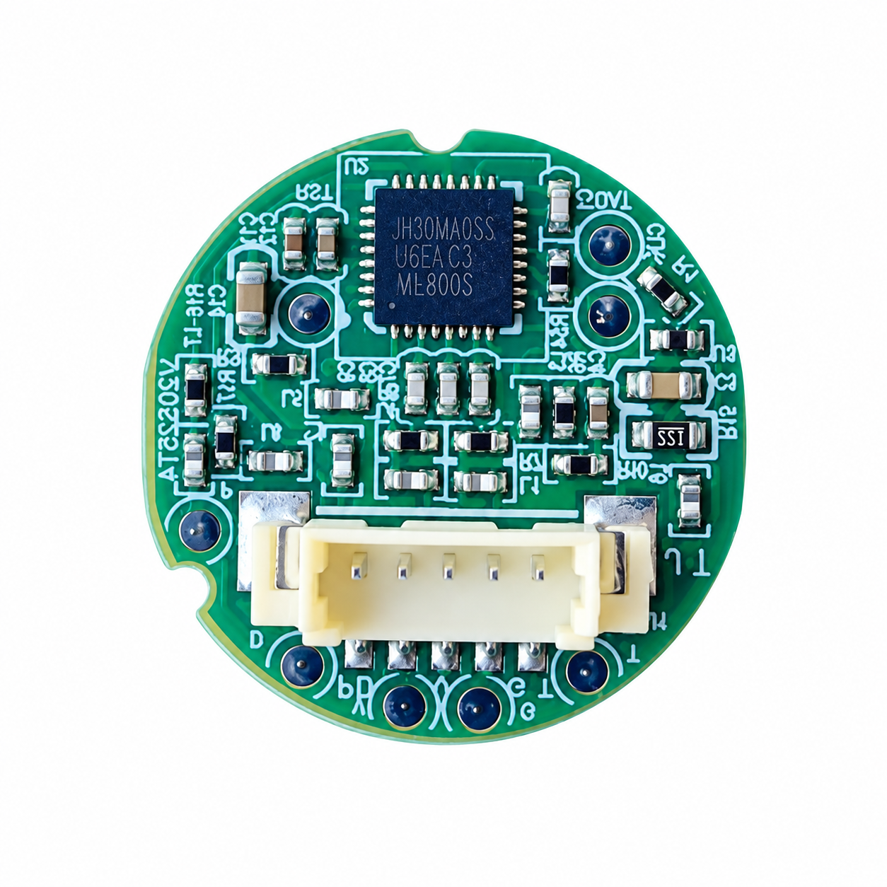
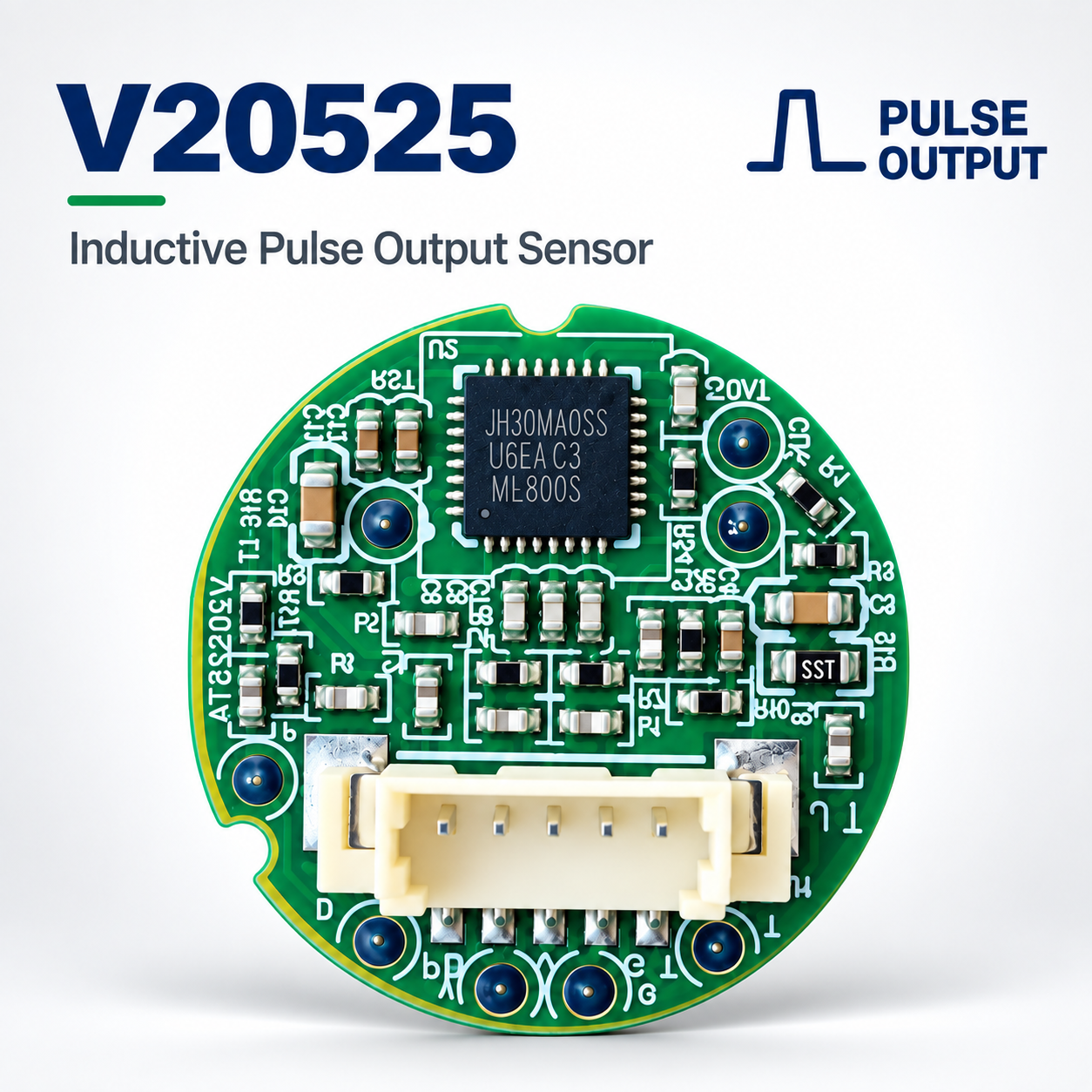
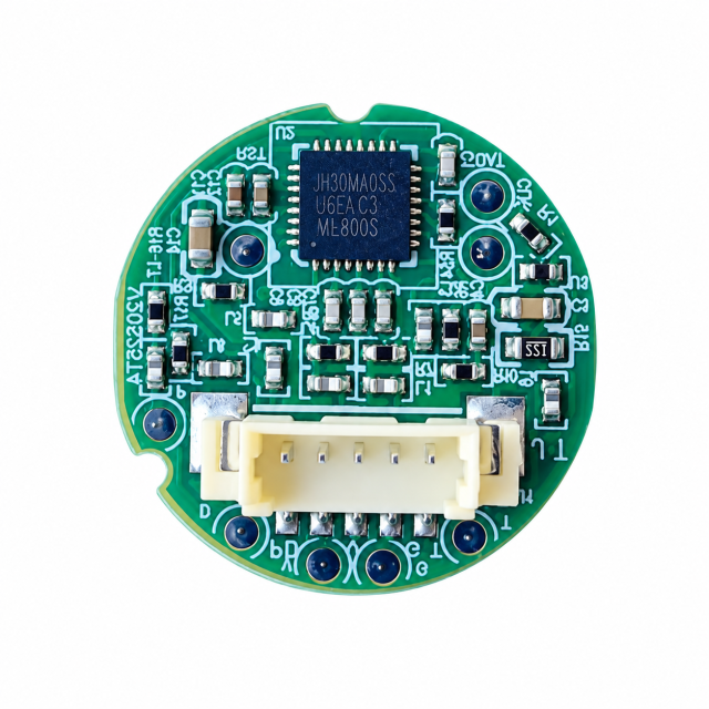
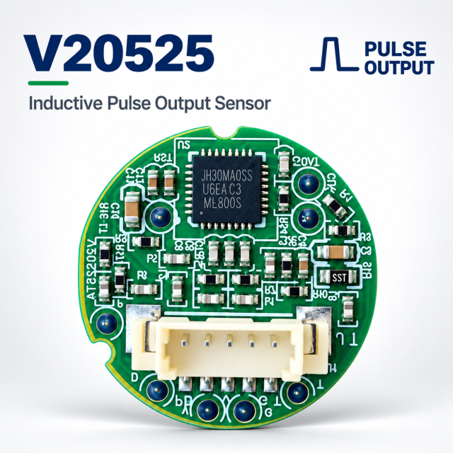
PCBA metering sensor is based on the unique metering chip WF8002. The coils are integrated into PCB board , it used to detect the number of turns with half-moon metal plate rotor which is below PCBA in right distance parallelly. (as PIC 1),it is widely applied in smart water meter/smart gas meter industries.Unique Algorithm/anti-magnetic/low power consumption/durable/reliable/compact/customizable are the features of PCBA count sensor.


PIC 1 The principle of PCBA count sensor
Ⅱ Main Features
|
Item |
Residential water meter |
Commercial water meter |
|
Type |
V23050 |
|
|
Pulse output mode |
OC/TTL |
|
|
Pulse width |
64ms |
|
|
Metering Mode |
Forward and Reverse |
|
|
Work Voltage |
3.0V~3.6V |
|
|
Work temp. |
- 15~55℃ |
|
|
Static power |
<4μA |
<11μA |
|
Working power |
<6μA |
<20μA |
|
Stable detect distance |
Less than 10 mm |
|
|
Max. Speed |
2.2 turns/sec. |
10 turns/sec. |
|
Storage temp. |
-40℃~ +90℃ |
|
|
Storage humidity |
5%~95%RH |
|
|
Other |
Sensor structure size is customizable |
|
(1)Signal output mode
This inductive sensor offers TTL(default)/OC output mode,other mode could be customized.
(2)Power Supply
It is external power supply,rated voltage: 3.0V~3.6V.The higher power supply voltage is, the longer detect distance would be.
The power consumption when PCBA sensor works.
The longest stable work distance between 304S/S rotor and PCBA sensor. Diameter 16mm、0.2mm thickness is the normal size of 304S/S rotor.The bigger diameter of 304S/S rotor is, the farther detect distance could be.
Rotor and PCB sensor’s flat must be concentric and parallel on a stable holder.
Ⅲ Function of PCBA sensor
(1) Signal intensity value output, to indicate the distance from PCBA sensor to S/S rotator in water meter.--READ from “T” pin
⚫convenient to keep consistency in production and testing
⚫used to confirm installation in expected place
(2) Accumulated pulses output(forward pulses and reverse pulses)--READ from “T”
⚫easy to judge the step(sync) issues between PCBA sensor and Main control board
⚫Completely anti-magnetic(overcome 10,000 Gs magnetic )
(4) Strong performance in anti-electromagnetic interference
⚫ implement unique anti-electromagnetic algorithm
Ⅳ Interface Specification
4.1 Interface View

4.1.2 Interface explanation
|
No. |
Mark / Pin |
Interface Definition |
|
1 |
- |
Ground for Vcc |
|
2 |
+ |
Positive pole for Vcc |
|
3 |
P / P1 |
Forward running pulse output |
|
4 |
D / P2 |
Reverse running pulse output |
|
5 |
T |
Control pin which is connected with main control board |
Ⅴ Structure size of PCBA sensor
PIC 4 Structure Size
Vertical Cut Size (xx±0.5mm),Horizontal-Size(xx±0.2mm)
Contact Person:Jing Yapeng WhatsApp/Wechat: +86 136 1650 5123 Jing@hangzhouweifeng.cn