In inductive smart water and gas metering systems, final metering performance is not determined by the metering IC alone.
The conductive metal target geometry, PCB sensing structure, sensing distance, rotation path, mechanical tolerance and available meter space all influence whether the system can reliably detect mechanical movement and generate stable forward, reverse and metering data.
For meter OEMs, the better development approach is not to search for one fixed sensing structure that fits every meter. Instead, the WF8002 Metering MCU SoC, sensing structure, conductive metal target and customer meter mechanism should be designed and validated as one complete system.
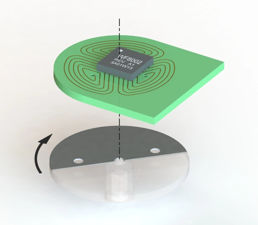
WF8002 itself is a Metering MCU SoC. The term WF8002-based non-magnetic inductive sensing solution refers to a system-level metering solution combining WF8002, the PCB sensing structure, conductive metal target and the customer's mechanical meter design.
This article explains general OEM integration and validation principles. It does not define one universal target size, one fixed sensing distance or a public PCB sensing-circuit design for every water or gas meter.
In a compatible meter design, WF8002 works with a PCB inductive sensing structure to detect a conductive metal target moving with the mechanical metering mechanism.
As the conductive target enters, leaves or changes its overlap with the sensing area, the electrical characteristics of the PCB sensing structure change.
WF8002 detects and processes these changes, converting mechanical movement into pulse or digital metering information that can be used by the upper-level system.
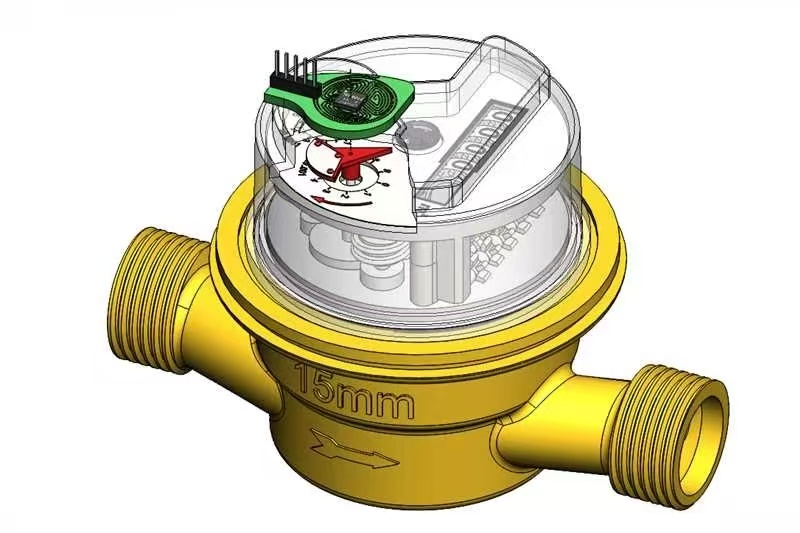
For a more complete explanation of the underlying inductive metering principle, see: Smart Water Meter Sensor Working Principle & Inductive Sensing Guide .
In real OEM projects, WF8002 does not interact with one standardized mechanical target.
Different meter platforms may have significant differences in:
For this reason, sensing-structure development should not be based on one fixed PCB geometry or one fixed mechanical distance.
The final sensing structure should be adapted to the actual customer meter and validated across mechanical tolerance, speed range and environmental conditions.
To protect Weifeng's core technology and engineering know-how, this public guide does not disclose proprietary PCB coil routing, sensing-circuit parameters or detailed circuit implementation.
A common misunderstanding is that WF8002 inductive metering requires one fixed metal target geometry.
In practice, the conductive metal target can be customized according to the customer's mechanical meter structure.
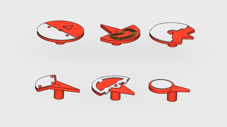
Different projects may use:
The final target design should consider:
Weifeng does not define one metal-target size as a universal standard for all customer projects. Final geometry and dimensions depend on the mechanical conditions of the target water or gas meter.
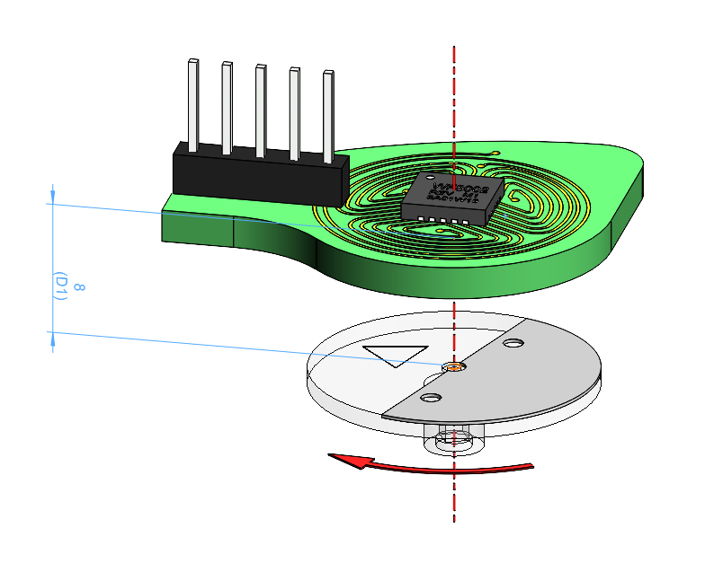
The relative distance between the PCB sensing structure and the conductive metal target is an important mechanical parameter affecting detection stability.
However, this distance cannot be defined independently of the actual meter mechanism.
A dimension shown in an engineering illustration represents the mechanical relationship of that particular design example. It should not be interpreted as a universal sensing distance for all WF8002 solutions.
The practical sensing distance can depend on:
A laboratory prototype working correctly does not guarantee that every mass-produced meter will behave identically.
The animation below shows the two tolerance checks used on the production line: radial eccentricity up to 0.50 mm while signal intensity holds at 60, and the allowed signal-intensity window of 30-300 with the coil centred.
Production can introduce multiple tolerance sources at the same time:
OEM validation should therefore include more than the nominal position. It should cover the realistic boundary conditions expected in production.
Mechanical operating speed can vary significantly depending on meter type, flow rate and application environment.
Low-speed validation should focus on:
High-speed validation should focus on:
Residential, commercial and industrial meters may require different validation conditions, so one fixed test speed should not be used to represent every meter application.
For additional discussion of WF8002 low-power metering design, see: WF8002 Ultra-Low-Power Metering Design .
When the PCB sensing structure and conductive metal target produce direction-dependent signal changes, a WF8002-based design can support forward and reverse movement recognition.
Engineering validation should cover:
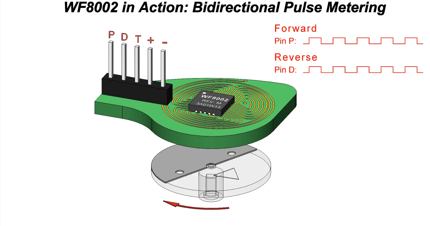
Explore a WF8002-based bidirectional metering solution: WF8002 Bidirectional Metering Solution .
To improve the efficiency of initial engineering evaluation, meter OEMs should provide as much mechanical and application information as possible.
| Project Information | Recommended Details |
|---|---|
| Meter Type | Water meter or gas meter |
| Application | Residential, commercial or industrial |
| Rotor Structure | Geometry, size, rotation path and mounting method |
| Metal Target | Existing structure or available design space |
| PCB Space | PCB outline, installation position and height limitation |
| Mechanical Distance | Nominal distance and possible tolerance range |
| Speed Range | Minimum and maximum rotation speed |
| Output Requirement | OC, TTL, forward/reverse pulse or digital interface |
| Communication | M-Bus, RS485, Wireless M-Bus, LoRaWAN, NB-IoT or host MCU |
A reliable production design should begin with the customer's real mechanical meter structure, not with a single IC or one ideal laboratory condition.
Mechanical Review -> Target Concept -> Sensing Structure Design -> Prototype -> Distance & Tolerance Test -> Low / High Speed Test -> Forward / Reverse Validation -> Environmental Test -> Production Validation
Testing one sample, one sensing distance or one speed is not sufficient to represent long-term stability under mass-production conditions.
For additional discussion of environmental reliability, see: WF8002 Smart Meter Reliability Design for Harsh Environments .
Hangzhou Weifeng supports smart water and gas meter manufacturers with WF8002 Metering MCU SoC and related metering solutions.
Typical project support includes:
To protect Weifeng's core technology and customer project intellectual property, proprietary PCB sensing circuits, detailed circuit parameters and selected design details are discussed only as needed during specific OEM project cooperation.
| WF8002 Metering MCU SoC
Explore WF8002 product architecture and smart metering applications. View WF8002 -> |
Pulse Output Sensor
Explore WF8002-based pulse-output sensing solutions. View Sensors -> |
Bidirectional Metering
Explore WF8002-based forward and reverse movement detection. View Solution -> |
No. Conductive metal target geometry and dimensions should be designed according to the customer's mechanical meter structure, movement path, sensing structure and direction-detection requirements.
A universal distance should not be defined independently of the project. The practical distance depends on the meter mechanism, conductive target, sensing structure, available installation space and tolerance conditions, and should be confirmed through prototype and complete-meter validation.
Public technical articles focus on system-level design principles. Detailed PCB sensing structures, circuit parameters and proprietary designs are part of Weifeng's engineering know-how and are supported according to the requirements of specific OEM projects.
Not necessarily. Different water and gas meters can vary in mechanical structure, rotation center, target geometry, mounting height and speed range. Mechanical adaptation and project-level validation are normally required.
With an appropriate sensing structure, conductive metal target and mechanical design, a WF8002-based solution can support forward and reverse movement recognition. Final performance should be validated in the target meter.
WF8002-based inductive metering is not simply a combination of one IC, one fixed metal plate and one fixed sensing distance.
Different customer water and gas meters have different mechanical structures. The conductive metal target, sensing structure, mechanical distance and tolerance conditions should therefore be adapted to the specific project.
For meter OEMs, the real engineering objective is to establish a validation system covering Mechanical Structure, Sensing Structure, Tolerance, Speed and Production Variation.
Send Hangzhou Weifeng your meter structure, rotor movement, available installation space, speed range and output requirements to request a WF8002 datasheet, sensor samples and an initial engineering evaluation.
Export Sales Manager: Jing Yapeng
Email: Jing@hangzhouweifeng.cn
Tel / WhatsApp / WeChat: 0086 136 1650 5123


