When a mechanical water or gas meter is upgraded with electronics, engineers usually focus first on whether the sensor can detect rotation reliably. Once that part works, another practical question appears very quickly: how should the metering signal be delivered to the Host MCU?
For WF8002-based pulse-output sensors, common interface choices include OC and TTL. The right choice depends on the Host MCU voltage domain, wiring arrangement, pulse-capture method, required forward/reverse information and the actual meter speed.
This article focuses on that interface problem. It is written for meter OEM engineers who need to connect the WF8002 metering layer to a controller, communication module or AMR/AMI system without losing valid metering events.
WF8002 itself is a Metering MCU SoC. It performs the underlying sensing, metering-data processing and movement-direction recognition.
OC or TTL pulse output is the interface used by selected WF8002-based sensor products to transfer processed metering information to the Host MCU or another upper-level electronic system.
Product parameters vary by sensor design and application. The numerical values in this article are reference values from current Weifeng product documentation and should always be checked against the latest datasheet for the selected model.
In a compatible meter design, a conductive target rotates with the mechanical metering mechanism and passes through the PCB inductive sensing area.
WF8002 detects the resulting signal changes, processes the movement information and determines the metering direction. Selected sensor products can then provide the processed result as positive/negative pulse outputs to the Host system.
The current Weifeng product catalogue lists the following reference parameters for selected pulse-output inductive sensor designs.
| Item | Residential Water Meter | Commercial Water Meter |
|---|---|---|
| Signal Output Mode | OC / TTL | |
| Reference Pulse Width | 64 ms | |
| Metering Mode | Forward and Reverse | |
| Working Voltage | 3.0–3.6 V | |
| Working Temperature | -15 to 55 °C | |
| Static Current | <4 µA | <11 µA |
| Working Current | <6 µA | <20 µA |
| Stable Detection Distance | Less than 10 mm | |
| Maximum Reference Speed | 2.2 rps | 8.0 rps |
Weifeng has developed different sensor structures for residential meters, commercial meters and higher-speed applications. The actual electrical and mechanical limits depend on the selected PCBA, sensing structure and meter mechanism.
OC stands for Open Collector.
In practice, the output transistor pulls the signal line low when active, while the Host side provides the pull-up voltage.
This can be useful when the meter sensor and Host controller need some flexibility in their logic-voltage relationship.
The Host engineer still needs to define:
TTL output provides an actively driven digital pulse with defined logic-high and logic-low levels.
If the output voltage is compatible with the Host MCU input, the interface can be relatively straightforward.
But engineers should still confirm:
The word "TTL" should never be treated as permission to connect the sensor directly to any MCU without checking the actual electrical specification.
In actual projects, the answer usually comes from the Host board rather than from the sensor alone.
| Question | OC | TTL |
|---|---|---|
| Need an external pull-up? | Typically yes | Normally no |
| Logic voltage flexibility | More flexible depending on pull-up design | Must match the defined output level |
| Host-side design | Requires pull-up and input design | Simple when voltage domains match |
For a new OEM design, it is better to define the Host MCU interface first and then select the corresponding WF8002 pulse-output sensor version.
Once the electrical interface is correct, the next issue is firmware.
The Host MCU may need to:
This sounds simple, but the implementation should reflect the actual meter speed.
A residential reference design operating up to around 2.2 rps places very different demands on the Host MCU compared with a commercial or higher-speed sensor design.
WF8002-based metering is not limited to a single undirected pulse stream.
The sensing structure can identify movement direction, allowing selected sensor products to provide positive and negative metering information.
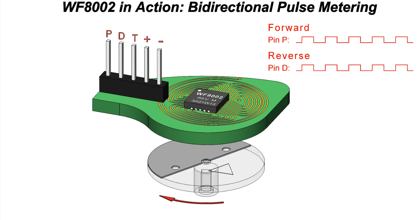
Positive and negative accumulated pulse information can also be useful during production when engineers need to check whether the electronic reading remains synchronized with the mechanical meter.
Explore: WF8002 Bidirectional Metering Solution .
The current product catalogue gives 64 ms as the reference pulse width for selected pulse-output sensor designs.
That number is useful for the Host MCU engineer, because the firmware must capture valid pulses reliably without treating the signal as noise or missing events.
Meter speed also matters. For example, the current reference product range includes:
This is why interrupt timing, polling interval and pulse-counting logic should be designed against the selected sensor version, not copied from another meter project.
In production hardware, the pulse signal may travel through a cable, connector or separate controller board before reaching the Host MCU.
Engineers should check:
A short bench connection may work perfectly, while the final harness behaves differently. The complete meter therefore needs to be tested in its actual electrical configuration.
| Validation Item | What to Confirm |
|---|---|
| Output Mode | OC or TTL matches the Host architecture |
| Logic Voltage | Compatible with Host MCU input limits |
| Pulse Timing | Firmware reliably captures the selected product pulse width |
| Maximum Speed | No missed counts at the project's maximum mechanical speed |
| Forward / Reverse | Direction records match actual mechanical movement |
| RF Coexistence | Pulse reading remains stable during wireless transmission |
Product-specific electrical parameters should always be checked against the latest datasheet before the Host MCU interface is finalized.
Visit the Weifeng Technical Download Center for current documentation.
| Pulse Output Sensors
Explore WF8002-based OC and TTL pulse-output sensor products. View Sensors -> |
Inductive Sensing Design
Learn how the sensing PCB, conductive target and meter mechanism are integrated. Read Design Guide -> |
Water Meter Remote Reading
See how pulse output can connect the metering layer to AMR / AMI systems. Read Remote Reading Guide -> |
OC is an open-collector switching output that normally uses an external pull-up. TTL is an actively driven digital output. The better option depends on the Host MCU and complete meter electrical architecture.
The current Weifeng catalogue lists 64 ms as the reference pulse width for selected pulse-output inductive sensor designs. Always confirm the value in the datasheet for the exact product being used.
Yes, selected WF8002-based metering solutions support forward and reverse movement recognition when used with the appropriate sensing structure and mechanical target design.
Not always. The required speed range, power consumption, PCB structure and mechanical installation can differ significantly between residential and commercial meter designs.
A reliable smart meter interface is more than simply producing a pulse.
The Host system must capture that pulse correctly across the actual voltage domain, speed range, wiring arrangement and forward/reverse operating conditions of the meter.
WF8002 provides the underlying metering information, while the final OC or TTL interface should be selected for the specific controller and meter architecture.
Send us your Host MCU voltage, interface requirements, meter type, maximum speed and forward/reverse requirements. Our team can help identify the appropriate WF8002-based sensor design.
Export Sales Manager: Jing Yapeng
Email: Jing@hangzhouweifeng.cn
Tel / WhatsApp / WeChat: 0086 136 1650 5123
Related reading
What a smart water meter PCBA should actually do: OEM selection and system design
Smart water meter sensors: working principle and inductive sensing
More guides: WF8002 metering blog
Need the WF8002 datasheet or a sample?
Tell us about your meter design and we will send the full datasheet, pinout and reference schematics, and review your OC/TTL pulse wiring with you.


