When customers first discuss a smart water meter PCBA, it is often understood as:
an electronic board that sends water meter data.
Once the project moves into real product development, however, the PCBA quickly becomes much more than a communication board.
For a mechanical water meter, a complete smart meter PCBA often needs to connect two very different worlds: the mechanical metering structure on one side, and the MCU, storage, communication and AMR / AMI system on the other.
A more useful question is: What layer is this PCBA responsible for, and does it actually fit my meter architecture?
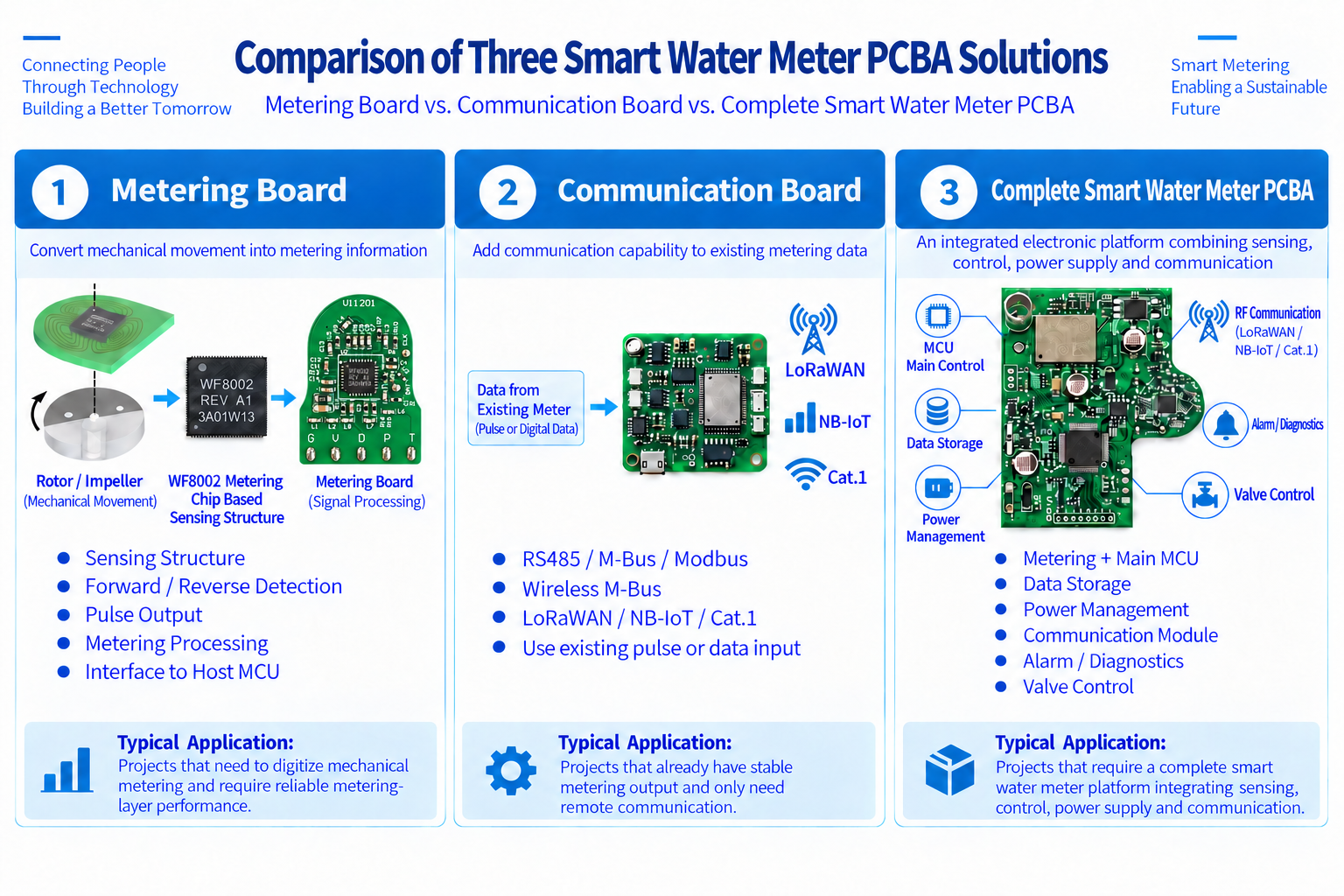
“Water meter PCBA” is a very broad term.
Two suppliers may both describe their product as a water meter PCBA while actually offering very different solutions.
A communication board mainly handles interfaces and remote connectivity such as:
It generally assumes that reliable metering data is already available from the existing meter.
This type of board is suitable for projects that already have a stable sensing or metering output and mainly need to add remote communication.
A metering board focuses more on the underlying metering layer, including:
Its main job is:
converting mechanical metering movement into stable electronic metering information.
A more integrated smart meter PCBA may further combine:
So before comparing quotations, it is useful to clarify:
Do I need a communication board, a metering board, or a complete smart meter PCBA?
Otherwise, two quotations may look similar while referring to completely different levels of functionality.
In a mechanical smart water meter project, the first job of the PCBA is not communication.
It is first necessary to solve:
Mechanical Movement → Electronic Metering Information
A mechanical water meter may include moving elements such as:
The electronic system first needs to identify real mechanical movement reliably.
In a solution using WF8002 Metering Chip Based Non-Magnetic Inductive Sensing, the basic signal path can be understood as:
The important point is not simply whether there is a sensor on the PCB.
The real engineering question is:
Can the PCB sensing structure, conductive target, mechanical position, rotor speed and assembly tolerance work together reliably?
If this layer is unstable, the MCU, communication module and AMR / AMI platform will not have a reliable data foundation.
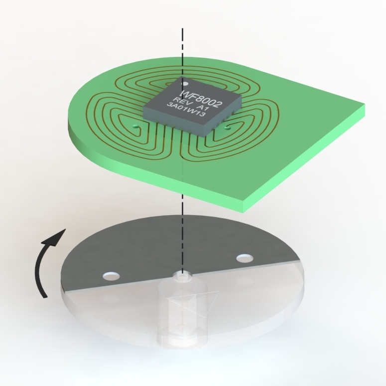
Detecting mechanical movement does not mean that every signal change should immediately be treated as a valid metering result.
The metering layer may also need to process:
This is one reason a true metering PCBA is different from a simple pulse converter.
A simple converter may perform:
Input Signal → Output Signal
A metering PCBA needs to perform:
Mechanical Movement → Valid Metering Information
WF8002-based modules can support forward and reverse information, accumulated rotation data, signal-strength information and module-separation status, all of which belong to the metering layer.
Many smart water meters also use an upper-level Host MCU.
The PCBA therefore needs to consider:
So the useful question is not simply:
“Does it have pulse output?”
A better question is:
Can the Host MCU receive every valid metering pulse reliably over long-term operation?
This becomes especially important in high-resolution mechanical meters.
As rotor speed increases, pulse frequency can also increase. A sensor that detects movement correctly does not automatically mean that the Host MCU will count every pulse correctly.
Many smart water meters are battery powered.
That means low-power PCBA design cannot be evaluated from one sensor-current number alone.
A complete power budget may include:
Therefore:
A low-power PCBA is not defined by one low-power component. It depends on the complete board and meter-level power architecture.
When comparing two solutions, purchasing and engineering teams should also confirm:
Is the quoted current the sensor current, or the complete system current?
These two numbers should not be compared as if they represent the same thing.
Once stable metering data is available, the project can move into the communication layer.
Depending on the application, the PCBA may be connected to:
The functional boundary is important.
WF8002 is responsible for the metering layer.
It is not a LoRaWAN, NB-IoT or Wireless M-Bus RF transceiver.
A more accurate system architecture is:
With this separation:
The value of a smart water meter is not limited to:
“reading a number remotely.”
Over long-term operation, a utility also needs to know:
Is this meter operating normally?
A smart meter PCBA may therefore need to handle diagnostic and alarm information such as:
This information can help the backend determine:
From this perspective, the smart meter PCBA is also an important entry point for meter-status information.
This is a very practical issue for water meter OEMs.
Mechanical meters from different manufacturers and product families can vary significantly:
For this reason, a real smart water meter PCBA is rarely:
one universal board that fits every mechanical meter without modification.
A more realistic approach is:
keep the core metering architecture consistent, while adapting PCB shape, interface, communication and mechanical integration to the target meter.
This is also why an experienced PCBA supplier should not only ask:
“How many boards do you need?”
It should first understand:
What kind of meter will this board actually be installed in?
| Layer | Main Function |
|---|---|
| Sensing | Detect mechanical movement |
| Metering | Forward / reverse detection, accumulation, filtering and abnormal-event recognition |
| Interface | Pulse / OC / TTL / Data |
| Host Control | MCU, storage and system logic |
| Power | Battery and low-power management |
| Communication | M-Bus / RS485 / W-MBus / LoRaWAN / NB-IoT |
| Diagnostics | Alarm / Battery / Status |
| Production Support | Test / Assembly / Consistency |
In a real product, these functions do not necessarily need to be located on one single PCB.
But from a complete system-design perspective, they normally all need to be considered.
Comparing only the unit price of two PCBAs can easily lead to the wrong conclusion.
A board that only handles communication and a board that includes the complete metering layer are fundamentally different products.
Purchasing and project teams should first ask:
Once these questions are clear, the quotation comparison becomes much more meaningful.
Engineers should go one level deeper and evaluate:
The same PCBA may behave very differently when installed in different mechanical meters.
That is why a real engineering evaluation cannot rely on the datasheet alone.
The complete PCBA must be evaluated together with the target meter architecture.
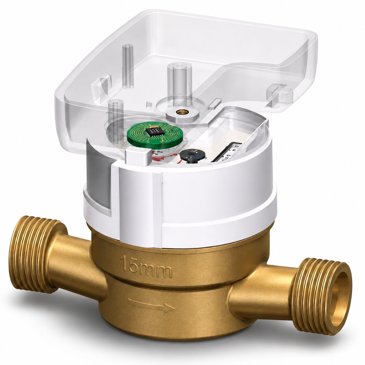
In a WF8002-based smart meter architecture, the system can be understood as:
WF8002 is mainly responsible for:
Metering sensing + metering processing
Its value is not in putting every smart-meter function into one chip.
Its role is to first convert mechanical metrology into reliable electronic metering information.
Once this layer is stable, the Host MCU and communication subsystem have a reliable data foundation.
For a water meter OEM, the more useful question is:
Does this PCBA truly fit my meter architecture?
A board that works in a demonstration is not automatically ready for long-term product integration.
A real project still needs to consider:
A complete smart water meter PCBA solution is therefore not simply a “functional board.”
It is the bridge between the mechanical metering system and the digital smart-meter system.
The real value of a smart water meter PCBA is not determined by the number of components on the board, or by how many communication protocols are listed in the specification.
What matters more is whether it can reliably connect:
Mechanical Metering → Reliable Digital Data → Communication → AMR / AMI
If sensing is unstable, faster communication does not solve the problem.
If the Host MCU and pulse interface are not properly matched, the data can still be unreliable.
If the power budget is not designed at system level, battery life cannot be guaranteed by one low-power component alone.
So when selecting a PCBA, a water meter OEM should ask:
Does this PCBA actually understand and fit my meter architecture?
Not simply:
“Does it support LoRaWAN or NB-IoT?”
PCB sensing structure, conductive target and mechanical integration considerations.
Read Mechanical Integration Guide ->OC / TTL, forward / reverse pulses and Host MCU integration.
Read Pulse Output Guide ->Learn how metering data connects to AMR / AMI systems.
Read Remote Reading Guide ->Send us your meter size / DN, mechanical structure, rotor or target information, available PCB space, Host MCU requirements and communication requirements. We can help evaluate a suitable WF8002-based metering PCBA architecture for your project.
Export Sales Manager: Jing Yapeng
Email: Jing@hangzhouweifeng.cn
Tel / WhatsApp / WeChat: 0086 136 1650 5123
Related reading
WF8002 pulse output: OC vs TTL and host MCU integration
Smart water meter sensors: working principle and inductive sensing
More guides: WF8002 metering blog
Planning a smart meter PCBA?
Send us your meter specification and annual volume. We will review the sensing, MCU and communication choices with you and send the full WF8002 datasheet and reference design.


