Getting a mechanical smart meter sensing demo to work is usually not the difficult part.
The rotor moves. The sensor produces a signal. A pulse appears on the oscilloscope.
But if the project is intended to become a real product, that is usually not where the validation should stop.
The more useful question is whether the entire metering chain remains stable from low-speed movement, start/stop and forward/reverse operation all the way to the maximum continuous rotor speed required by the project.
The focus here is metering sensing validation during mechanical smart meter development: how to verify the mechanical-to-digital metering chain before entering complete regulatory or metrological testing.
When a new mechanical meter arrives, the first step is usually not to connect an oscilloscope.
Start by understanding the meter itself.
At minimum, it is useful to clarify:
If these points are not clear, a clean pulse waveform alone does not necessarily mean the complete meter architecture is correct.
In a mechanical smart meter, the mechanical movement itself is the source of the electronic metering information.
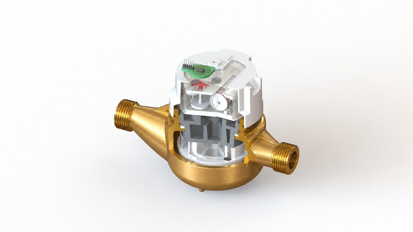
At normal speed, many sensing solutions can appear to work well.
The more interesting behavior often appears when the rotor slows down.
At low speed, mechanical movement may not be perfectly uniform.
The rotor may:
The real question is:
Does one real mechanical metering event produce only one valid electronic metering event?
If the sensing response is too weak, real movement may be missed.
If the system is overly sensitive around a threshold position, small mechanical oscillations may be interpreted incorrectly.
So the purpose of low-speed testing is not simply to prove that the sensor is “sensitive.”
The more useful question is:
Does the metering decision remain clean and stable during slow and non-uniform mechanical movement?
Laboratory testing often uses continuous rotation.
Real pipe conditions may be less predictable.
Pressure variation, small vibration or stopped flow can leave the mechanical mechanism close to the sensing threshold.
That condition is worth checking separately.
A simple validation sequence can be:
Then observe:
This test looks simple, but it can reveal interface behavior that may not appear during a basic constant-speed rotation test.
If the final product requires:
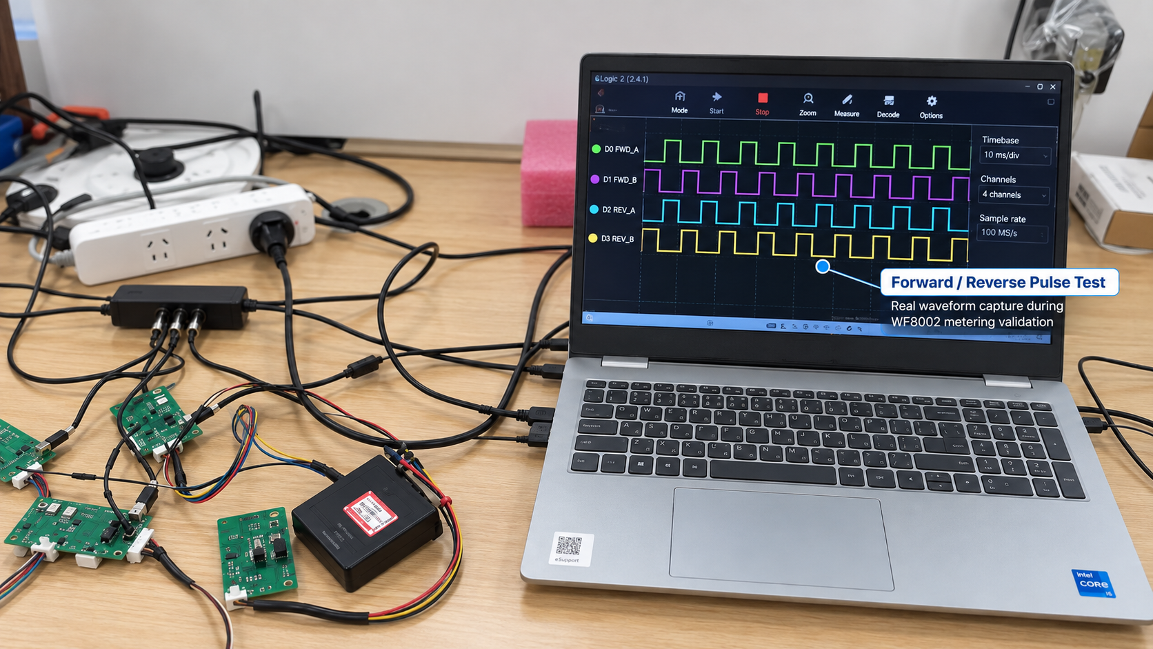
forward and reverse operation should be included in the sensing validation from the beginning.
A straightforward test sequence is:
Key points to observe include:
With WF8002 Metering Chip Based Non-Magnetic Inductive Sensing, forward and reverse information is part of the metering layer itself, rather than something the communication layer has to infer later.
Low-speed validation answers one question:
Can slow and complex mechanical movement still be interpreted cleanly?
High-speed validation answers another:
Can the sensing system and the complete pulse chain keep up?
Maximum rotor speed can vary significantly between meter projects, so one universal speed value should not be applied to every meter.
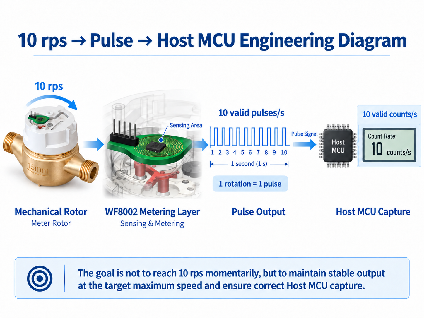
For some high-resolution reference designs, if the project requires 10 rps and defines:
1 rotation = 1 valid pulse
then the complete chain must continuously support:
The important point is not reaching 10 rps momentarily.
The real objective is:
Maintain complete and stable counting during continuous operation at the target maximum rotor speed.
This is why sensing speed, pulse timing and Host MCU capture strategy should be validated together.
Many validation sessions stop at the oscilloscope.
The sensor produces 100 pulses.
Everything looks correct.
But in the final product, the oscilloscope is not doing the counting.
The Host MCU is.
So the complete chain should also be checked:
One direct validation method is to rotate the mechanical side for a known number of cycles, for example 1000 rotations.
Then record:
The final comparison is simple:
Do these counts remain consistent with the actual mechanical movement?
This is closer to the final product than looking at the pulse waveform alone.
In a real smart meter, the metering layer does not operate alone in a perfectly quiet electrical environment.
The same product may also include:
So one practical complete-meter test is:
Keep mechanical metering running while the RF subsystem is transmitting normally.
Then observe:
This does not assume that RF activity will cause a problem.
It simply reflects the fact that both subsystems will operate together in the final product.
Battery-powered products introduce another real-world condition:
A new battery and a battery after years of service do not operate under exactly the same conditions.
Metering validation should therefore not always remain at nominal supply voltage.
Useful conditions can include:
The objective is not to create the longest possible test list.
The important question is:
Does the metering chain remain stable when several realistic operating conditions occur at the same time?
If the project can provide sensing signal-strength information, that data can be useful beyond simply confirming whether detection occurs.
It can help observe:
During engineering development, a reference range can first be established.
During pilot production, multiple samples can then be compared against that range.
This provides more information than a simple:
PASS / FAIL
result alone.
| Validation Layer | What to Check |
|---|---|
| Mechanical Validation | Rotor, target, position, speed and tolerance |
| Metering Validation | Low-speed detection, forward/reverse, start/stop and high-speed continuous counting |
| Interface Validation | Pulse width, OC / TTL, cable, connector and Host MCU capture |
| System Validation | Lower voltage, RF activity and complete-meter operation |
This layered approach makes troubleshooting easier when an unexpected result appears.
Instead of treating the entire meter as one black box, the problem can be traced back to the mechanical, metering, interface or system layer.
Formal water meter metrological verification is governed by established standards and test procedures.
ISO 4064-2:2024 covers water meter type evaluation and initial verification test methods, including complete water meters as well as relevant metering units such as measurement transducers and calculators.
ISO 4064-2:2024 — Water meters — Part 2: Test methods ->
OIML R49-2:2024 also provides water meter test methods covering metrological and technical evaluation.
OIML R49-2:2024 — Water meters for cold potable water and hot water — Part 2: Test methods ->
ISO 4064 and OIML R49 address formal metrological and compliance testing. The sensing validation discussed in this article is an engineering-development activity: strengthening the mechanical-to-digital metering chain before entering complete standard-based testing.
Validation of a metering sensing solution should not stop at:
“Does it work?”
A more useful set of questions is:
Under which mechanical conditions does it work? What happens at low speed? At high speed? During direction changes? And what does the Host MCU finally receive?
In a mechanical smart meter, stability does not belong to one electronic component alone.
It belongs to the complete chain:
Once this chain is clear and stable, communication and AMR / AMI systems have a much more reliable starting point.
Learn how the PCB sensing structure, conductive target and mechanical meter structure work together.
Read the Mechanical Integration Guide ->OC vs TTL, forward/reverse pulses and Host MCU integration.
Read the Pulse Output Guide ->Learn more about the WF8002 metering layer for smart water and gas meter applications.
View WF8002 ->Send us your meter type / DN, mechanical structure, conductive target, rotor speed range, forward/reverse requirement and Host MCU interface. We can discuss an appropriate WF8002-based sensing and validation approach for the actual meter structure.
Export Sales Manager: Jing Yapeng
Email: Jing@hangzhouweifeng.cn
WhatsApp / WeChat: +86 136 1650 5123
Product line: Inductive metering sensors — WF8002-based, non-magnetic, anti-magnetic/RF interference, RoHS 2.0, samples and datasheets available.


