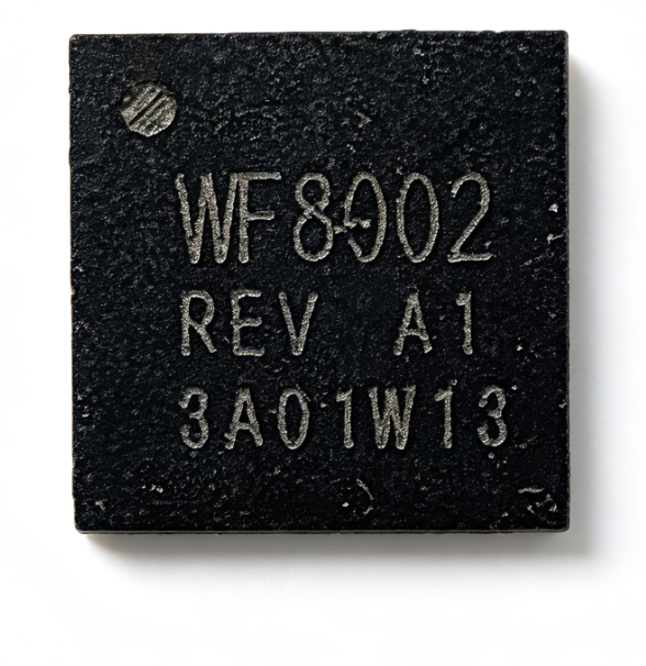
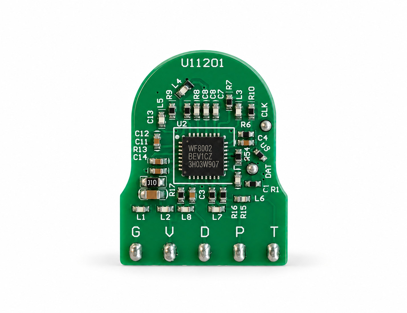
In mechanical water meter digitalization, detecting rotation is only the first step.
Once the sensing electronics are integrated into a real meter, PCB position, conductive target alignment, mechanical tolerance and assembly consistency can all influence the actual sensing condition.
A stable metering system must first understand the actual condition of each assembled meter, and then continue adapting to changes during long-term operation.
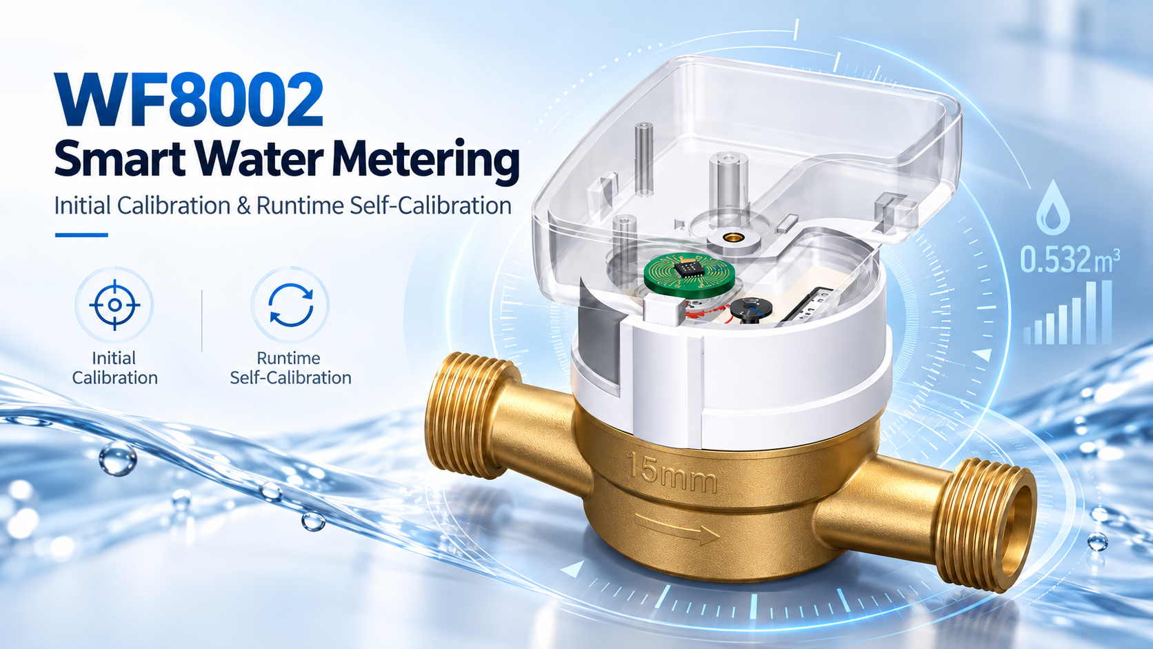
Electronic metering in a mechanical water meter does not operate independently from the meter structure.
In WF8002 Metering Chip Based Non-Magnetic Inductive Sensing, mechanical movement is converted into electronic metering information through the conductive target, PCB sensing structure and metering signal-processing chain.
Even when the same chip and basic sensing design are used, real assembled meters may still differ in:
These differences can appear directly in the sampled sensing signals.
This is why the metering system first needs to establish what “normal” looks like for the actual assembled meter.
When the system starts for the first time, the internal metering parameters are still based on default settings.
Before entering stable operation, the system needs to observe the real movement of the conductive target within the actual meter structure.
Initial calibration therefore helps the system understand:
The objective is to establish metering parameters that match the actual mechanical and sensing condition of the assembled meter.
WF8002-based inductive metering uses multiple sensing channels to observe how the conductive target moves through the sensing area.
As the target rotates, the received sensing energy changes across the channels in a defined sequence.
After signal sampling and processing, the metering algorithm can use these changes to determine:
In an ideal structure, the channel signals should show clear and consistent relationships.
In real production, however, mechanical offset, non-concentric installation or variation in the sensing structure may change the actual signal relationship.
Calibration therefore evaluates the combined condition of the mechanical structure, sensing structure and electronic sampling system.
Signal strength can be used as an engineering indicator of how clearly the mechanical movement appears in the electronic sensing data.
It may vary with factors such as:
For example, increasing the distance between the conductive target and sensing structure generally reduces the available sensing signal.
Misalignment may also cause one sensing channel to behave differently from the others.
Once the initial calibration has established a reliable reference, signal strength and channel consistency become more useful for engineering evaluation.
A mechanical water meter is not a perfectly static system throughout its entire service life.
Real operating conditions may change over time due to:
If the system relied only on one fixed parameter set established during production, the operating margin could gradually change as the real meter condition changes.
Runtime self-calibration therefore allows the system to optimize internal parameters according to the actual operating condition.
Runtime self-calibration takes place during normal meter operation.
As the conductive target continues rotating, the metering system receives new real-world sensing data.
This information can then be used to continuously optimize the internal metering state.
The important distinction is:
Runtime self-calibration does not replace initial calibration. It builds on the established baseline and continues adapting during real operation.
Not necessarily.
A temporary self-calibration exception may indicate that abnormal conditions occurred during a particular rotation, such as:
For this reason, the self-calibration status should be treated as useful operating-state information, rather than automatically being interpreted as a failed metering event.
| Item | Initial Calibration | Runtime Self-Calibration |
|---|---|---|
| When | Before stable operation | During normal operation |
| Main Purpose | Establish the initial metering baseline | Continuously optimize operating parameters |
| Data Source | Real mechanical rotation and sensing data | Real sensing data during actual operation |
| Engineering Value | Understand the assembled meter | Adapt to changes during long-term operation |
Calibration and sensing data are not only useful during R&D.
Once the mechanical design is validated, production still needs a way to identify samples that deviate from the expected condition.
For example, unusual differences between sensing channels may indicate:
Therefore, calibration status, signal strength and channel consistency can become useful engineering references for production quality control.
One of the most common questions in inductive metering projects is:
“What is the maximum sensing distance?”
But for real smart meter integration, this question alone is incomplete.
Stable operation depends on the combined effect of:
The better engineering question is whether the complete meter has enough stable sensing margin under its actual mechanical and operating conditions.
WF8002 should not be understood as a simple “metal present / metal absent” detector.
A more complete view of the metering chain is:
This is the role of WF8002 Metering Chip Based Non-Magnetic Inductive Sensing:
converting real mechanical movement—with real tolerances and real operating variation— into stable and repeatable electronic metering information.
Learn more about the core metering chip used in WF8002-based inductive sensing solutions.
View WF8002 ->Explore a complete WF8002-based sensing solution for forward and reverse metering applications.
View the sensing solution ->Explore WF8002-based pulse-output sensing options for smart water and gas meters.
View pulse output sensors ->Smart meter sensing stability is not determined the moment the first pulse appears.
Initial calibration answers:
“What does normal look like for this assembled meter?”
Runtime self-calibration answers:
“How should the metering system continue adapting as real operating conditions change?”
For WF8002 Metering Chip Based Non-Magnetic Inductive Sensing, calibration is not an isolated additional function.
It is part of the process that helps convert real mechanical movement into stable electronic metering information.
Send us your mechanical meter structure, conductive target design, sensing PCB requirements and metering application. Our team can discuss the appropriate WF8002 sensing and integration approach for your project.
Export Sales Manager: Jing Yapeng
Email: Jing@hangzhouweifeng.cn
WhatsApp / WeChat: +86 136 1650 5123