Adding remote reading to a G25 or G40 gas meter starts with a pulse output, but a pulse alone does not make a metering system. The system also has to know how much volume each pulse represents, whether the collected volume is at working conditions or base conditions, and how forward and reverse flow are recorded separately.
If any one of these is configured incorrectly, the reading can drift continuously, and a single uplink is rarely enough to reveal the cause.
This guide covers commercial gas meters with a mechanical counter, a pulse output or an integratable sensing structure. Specific values must always be confirmed against the target meter datasheet, nameplate and local metrology requirements.
Confirm three things first: the pulse weight is fixed by the gear train and target position inside the meter; volume conversion must be assigned to the meter, an EVC or the back office; and the data model must carry direction, timestamps and counts retained through power loss.
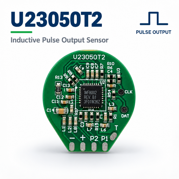
G25 and G40 normally refer to nominal flow ratings of 25 m³/h and 40 m³/h. That does not mean that every meter in the same rating shares the same maximum flow, minimum flow, pulse weight or operating pressure.
In Apator UG documentation, for example, UG G25 has a nominal flow of 25 m³/h and a maximum flow of 40 m³/h, while UG G40 can reach 65 m³/h. Configurations from other manufacturers and structures must be confirmed from their own model documents.
| Item | What to confirm at the design stage |
|---|---|
| Meter type and structure | Diaphragm meter, rotary meter and the exact model; never infer the interface from G25/G40 alone. |
| Flow parameters | Qmax, Qmin, Qt, permitted installation direction and operating pressure range. |
| Pulse interface | Whether it is a factory option; output type, pulse weight, maximum frequency and electrical isolation requirements. |
| Metering boundary | Whether the pulses are used for monitoring, remote reading or billing; which certification and sealing constraints apply. |
On retrofit projects, check the factory-prepared interface and any approved pulse accessory first. Without a prepared interface, adding a sensing structure can involve mechanical, metrological and certification work, and it should not be treated as a universal add-on.
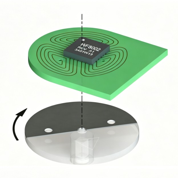
In a mechanical meter, the measuring element drives the register wheels or pointers through a gear train. A target mounted on a shaft or an indicator disc is detected by the sensor, and each detected rotation event is converted into an electrical signal. The complete signal chain can be summarised as:
Let w be the pulse weight, the volume represented by one pulse in m³/pulse, and K the number of pulses per cubic metre.
For example, if w = 0.1 m³/pulse, then K = 10 pulses/m³. This relationship holds only when the units are defined consistently. Here K means pulses per unit volume, not the discharge coefficient used in differential-pressure flow measurement.
The pulse input has to cover the highest frequency the meter can produce at maximum flow. With Q in m³/h and w in m³/pulse:
For a G40 model with Qmax = 65 m³/h and a pulse weight of 0.1 m³/pulse, the theoretical maximum frequency is about 0.181 Hz, or roughly 650 pulses per hour. At the same flow with a pulse weight of 0.01 m³/pulse, the maximum frequency rises to about 1.81 Hz. These numbers only illustrate the formula; every project must use the parameters from the target meter datasheet.
Low frequency does not mean there is no risk of lost counts. In the field, the more common causes are contact bounce, an unsuitable input debounce setting, software blocking during radio transmission, an accumulator that is not saved before power loss, and pulse edges that are not handled during restart or firmware upgrade. Validate the receiving end at the maximum frequency, the shortest pulse width and the worst supply condition.
Gas volume changes with temperature and pressure. The volume measured at working conditions, Vm, is not necessarily equal to the volume at the agreed base conditions, Vb. A simplified conversion is:
Here Pm and Pb are the absolute pressures at the measurement point and at base conditions; Tm and Tb are absolute temperatures and must be in kelvin; and Z is the gas compressibility factor. Base temperature, base pressure and permitted conversion methods differ between markets, so no single regional base condition should be treated as a global default.
Volume correction can be carried out by a meter with temperature or temperature and pressure sensors, by a separate electronic volume corrector (EVC), or by an approved back-office system. When the data flow is designed, the meaning of each output must be explicit.
| Output data | What the system should retain |
|---|---|
| Working volume | Raw pulse total, pulse weight, measurement timestamp and unit. |
| Base volume | Definition of base conditions, correction source, correction factor or a traceable correction record. |
| Direction and events | Forward and reverse totals, reverse-event timestamps, sensor status and power-loss records. |
Avoid double correction: if the meter or the EVC already outputs base volume, the back office must not apply the correction factor again. Conversely, if the meter only outputs working volume, the back office must have the data and the approved rules needed to complete the conversion. Where billing is involved, follow the regulations, certification route and applicable standards of the target market.
Storing only a single total pulse value loses information about flow direction. Where reverse flow is possible in the meter or in the application, the interface and the data structure should carry an explicit direction state and separate forward and reverse accumulators. Where LF and MF dual pulses are used, each channel should keep its own identifier and pulse weight.
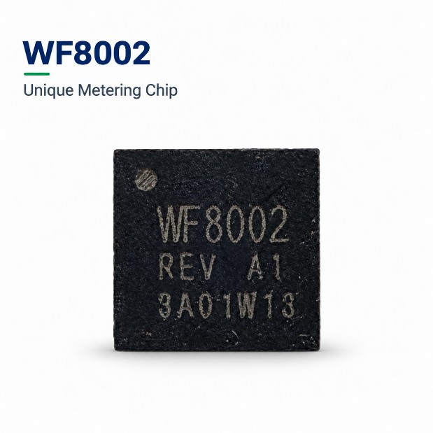
Non-magnetic inductive sensing uses a conductive target and a PCB sensing structure instead of a permanent magnet triggering a reed switch, and it can be one of the technical options for a new design. It is not a plug-and-play replacement for every existing meter: target shape, distance, offset tolerance and whole-meter certification all need project-level validation.
| Sensing method | Typical considerations | Where it fits |
|---|---|---|
| Reed switch | Mature structure and usable in factory-prepared pulse accessories; contact ratings, electrical parameters and the magnetic actuation structure must be checked. | Repair or retrofit, especially where an approved accessory already exists. |
| Hall sensor | Requires a magnetic field and a supply; mounting position, magnet and the external magnetic environment all enter the design. | Applications that already have a magnetic target and can support its supply and signal processing. |
| Non-magnetic inductive | Consists of a chip, PCB coil, conductive target and mechanical structure; spacing, target motion and electrical output must be validated. | New meter designs or complete upgrades where bidirectional metering and non-magnetic detection need to be evaluated. |
Selection should not be based on component price alone. Evaluate the mechanical interface of the whole meter, flow range, direction detection, power consumption, installation space, EMC, maintenance approach and metering certification boundary at the same time.
Before a prototype build or a field trial, the following items should be part of the design review:
There is no single value that applies to all G25 models. Check the datasheet, nameplate or factory pulse-module documentation of the target meter.
No. Maximum flow differs between models. 65 m³/h is a model parameter taken from some product documentation and cannot be inferred from the G40 rating alone.
Not necessarily. Display resolution and pulse weight are two independent parameters and must be confirmed separately.
It depends on the meter and system design and on the applicable regulations. Wherever it sits, the volume type, base conditions and the party responsible for correction must be identified, and double correction must be prevented.
It cannot be treated as a universal pin-compatible swap. WF8002 is a metering IC; a complete non-magnetic inductive solution also needs a matched coil PCB, a conductive target, mechanical space and project validation.
No. Direction detection is one capability of the sensing and data-processing chain. Whole-meter metering performance and certification still have to be validated through the complete instrument and the applicable certification route.
Integrating pulses into a G25/G40 commercial gas meter starts with defining the meter parameters, the pulse weight, the direction state and the volume conversion. Only then can the sensing structure and the communication scheme be chosen.
For new designs, a WF8002-based non-magnetic inductive metering solution can be evaluated together with the chip, sensing PCBA, conductive target and meter structure. The final configuration must pass the design validation of the target meter and the applicable certification process.
If you are developing or upgrading a G25/G40 gas meter, prepare the meter model, nameplate photos, target or installation-space drawings, target pulse weight, output interface, supply and communication requirements, and discuss the project with the WEIFENG team.
Email: Jing@hangzhouweifeng.cn
WhatsApp / WeChat: +86 136 1650 5123
Note: the applicable version of each standard, the regulatory requirements and the whole-meter certification route should be confirmed by the meter manufacturer together with the local compliance and metrology team. This article provides general engineering information and does not replace manufacturer specifications, type approval or local regulatory requirements.


