In mechanical smart water meter projects, communication is often the first topic people discuss: LoRaWAN, NB-IoT, Wireless M-Bus, or the final AMR / AMI platform.
But before any of that, there is a more basic engineering question:
The higher the mechanical metering resolution, the faster the rotor may need to move — and the sensing system must be able to keep up reliably.
0.1L, 1L and 10L are not electronic accuracy settings defined by the sensor. They first reflect different mechanical meter resolutions or mechanical metering designs. For the sensing layer, the real task is to detect the actual rotor movement continuously and convert it into stable, valid metering pulses.
The 0.1L, 1L and 10L values discussed in this article refer first to the mechanical meter's own metering resolution or mechanical design. The sensor does not simply “select a 0.1L electronic resolution.” Instead, it must reliably detect the real rotor speed produced by that mechanical meter and provide the corresponding metering pulses.
In a mechanical water meter, metering resolution comes from the mechanical metering structure itself.
Different meter types, flow ranges and mechanical architectures can use different metering resolutions.
For example, some residential mechanical meters may use a 1L-level metering resolution, some high-resolution designs may use 0.1L, while some large-diameter meters may use a 10L-level mechanical metering design.
These differences are not only numerical.
They directly affect:
That is why the mechanical meter's own resolution is one of the first parameters to confirm when selecting a sensing solution.
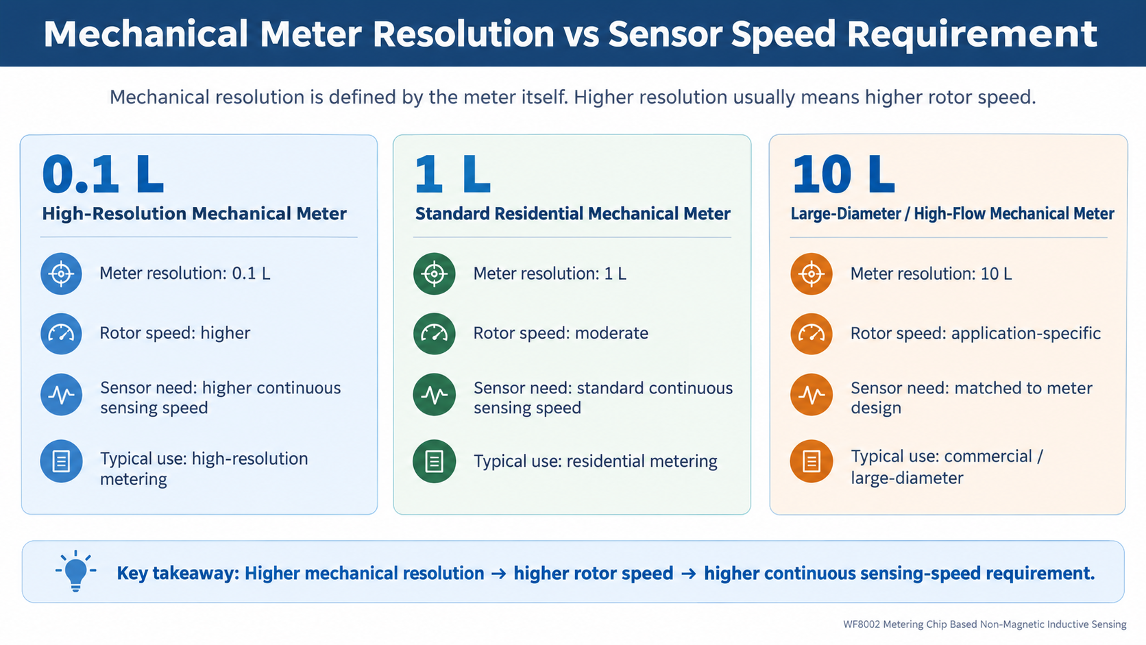
When a mechanical meter uses a higher-resolution metering design, the rotor may need to complete valid movements more frequently at the same flow rate.
For example, a 0.1L high-resolution mechanical meter needs to represent smaller increments of water volume than a lower-resolution design.
For the sensing system, this means:
So the real engineering question is not only whether the sensor is “sensitive enough.”
The more important question is whether it can continuously track every real mechanical event at the target rotor speed.
In a solution using WF8002 Metering Chip Based Non-Magnetic Inductive Sensing, continuous high-speed detection capability becomes an important engineering consideration for high-resolution mechanical meter applications.
rps means rotations per second.
10 rps means:
the mechanical rotor continuously rotates 10 times in one second.
If the current meter and sensing design defines:
1 rotation = 1 valid pulse
then 10 rps corresponds to:
10 rotations/s = 10 pulses/s
In other words, the sensing system needs to complete 10 valid detections within one second and provide 10 stable metering pulses that the Host MCU can reliably capture.
The key point is continuous stable output, not simply detecting a high-speed rotation once during a short test.
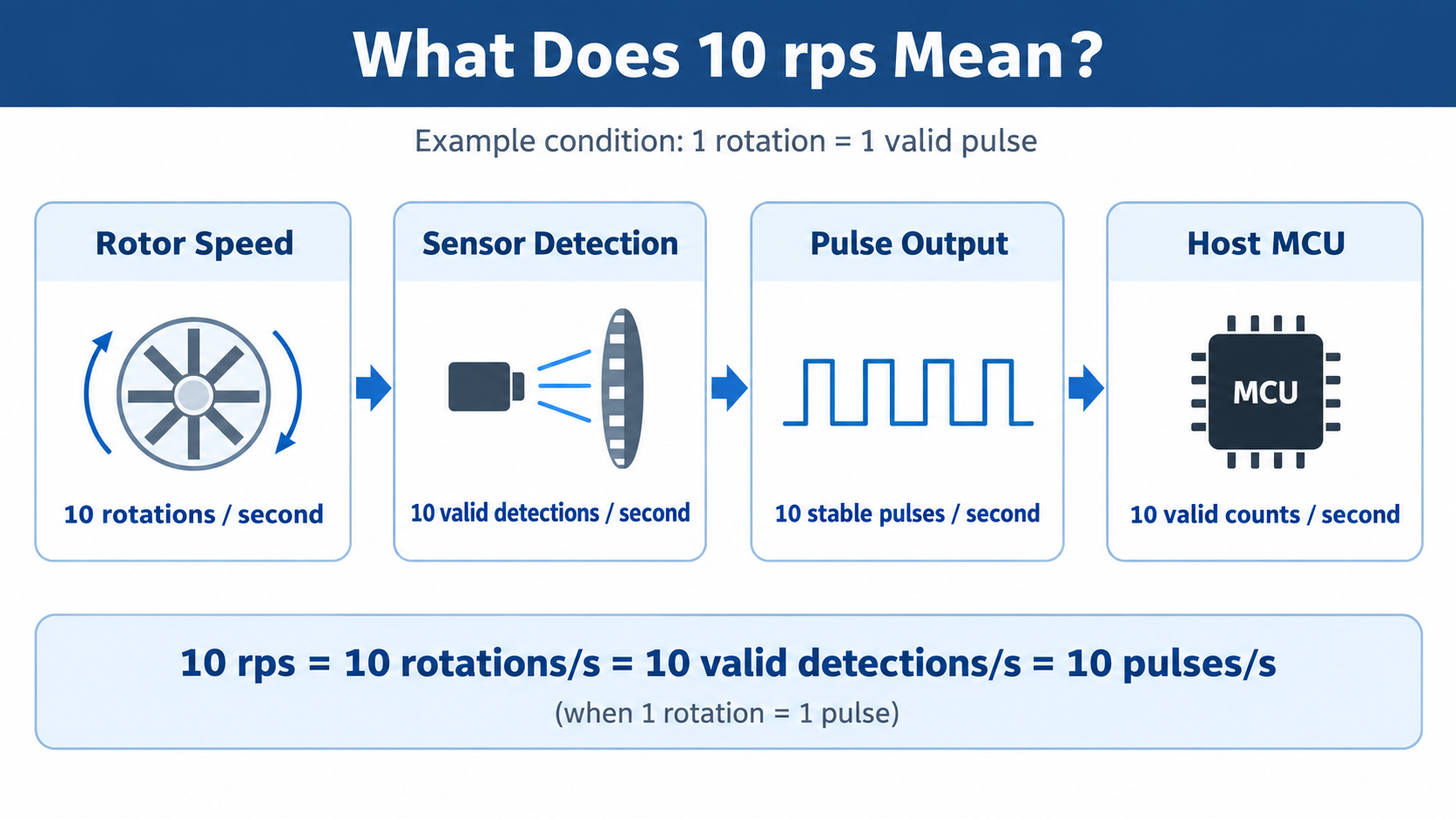 When the design defines 1 rotation = 1 valid pulse, 10 rps corresponds to 10 stable metering pulses per second.
At low speed, many sensing solutions may appear to work correctly.
But once the application moves into a higher-resolution mechanical meter with faster rotor movement, continuous operation becomes the real test.
Engineers need to confirm:
This is why sensor performance should not be judged only by a parameter such as:
“What is the maximum sensing distance?”
For high-resolution mechanical meters, another equally important question is:
At the target maximum rotor speed, can the system continuously provide complete and stable metering pulses?
WF8002 does not redefine the mechanical meter's 0.1L, 1L or 10L metering resolution.
It sits between the mechanical metering structure and the upper-level electronic system.
WF8002 Metering Chip Based Non-Magnetic Inductive Sensing uses the PCB sensing structure to detect the movement of a conductive target moving with the mechanical rotor, then converts those valid mechanical events into metering information that the electronic system can process.
In high-resolution mechanical meter applications, the metering layer may need to support:
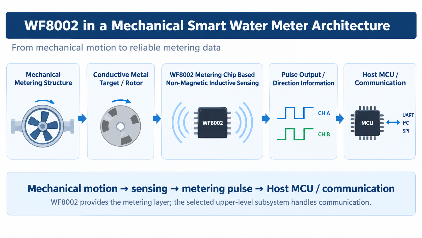
The metering chain does not end when the sensor outputs a pulse.
As rotor speed increases, pulse frequency also increases.
The Host MCU should therefore confirm:
For more detail on OC / TTL, forward/reverse pulse output and Host MCU integration, see:
WF8002 Pulse Output Guide: OC vs TTL, Forward/Reverse Pulses and Host MCU Integration ->
If a mechanical water meter is being upgraded with electronic metering or smart connectivity, it is useful to confirm the mechanical-side parameters first.
| Project Parameter | Why It Matters |
|---|---|
| Mechanical Meter Resolution | Defines the meter's mechanical metering granularity |
| Rotor Maximum Speed | Defines the continuous sensing speed required from the sensor |
| Pulses per Rotation | Determines the final pulse frequency |
| Forward / Reverse Requirement | Determines whether bidirectional metering and direction recognition are required |
| Host MCU Interface | Determines how the pulse output is matched to the upper-level controller |
Once these parameters are clear, it becomes much easier to determine whether a sensing solution is suitable for the target mechanical meter, rather than evaluating the project from one isolated specification.
Learn how PCB sensing structure, conductive target and mechanical structure work together.
Read Mechanical Integration Guide ->OC / TTL, forward/reverse pulses and Host MCU integration.
Read Pulse Output Guide ->Learn how metering data can be connected to AMR / AMI systems.
Read Remote Reading Guide ->Public industry documentation also shows that different mechanical water meters use different metering structures, pulse interfaces and application requirements.
Diehl Metering — Pulse Transmitter Technical Data
View Diehl Official Technical Data ->
ZENNER — Mechanical Water Meter Product Information
View ZENNER Official Product Information ->
External references are included for general industry and technical context only. They do not imply a commercial partnership with Hangzhou Weifeng.
No. In this context, they first refer to the mechanical meter's own metering resolution or mechanical metering design. The sensing system must then detect the actual rotor movement and provide stable metering output.
Higher mechanical resolution usually means that valid mechanical movements occur more frequently at the same flow rate. The sensing layer therefore needs stronger continuous high-speed detection capability.
If the project defines 1 rotation = 1 pulse, then 10 rps corresponds to 10 valid pulse outputs per second.
WF8002 Metering Chip Based Non-Magnetic Inductive Sensing detects valid mechanical rotor movement and provides stable metering pulse and direction information to the upper-level electronic system.
For a 0.1L high-resolution mechanical water meter, the real challenge is not simply having a “higher-resolution” number on a specification sheet.
The more practical engineering question is:
At the target maximum rotor speed, can the sensing system recognize every rotation continuously and provide stable metering pulses?
Only after the sensing layer is stable can the Host MCU, communication module and AMR / AMI system have a reliable data foundation.
This is where WF8002 Metering Chip Based Non-Magnetic Inductive Sensing provides value in high-resolution mechanical water meter applications.
Send us your mechanical meter resolution, rotor structure, maximum speed, pulses-per-rotation definition, Host MCU interface and communication requirements. We can help evaluate a suitable WF8002-based metering solution for the project.
Export Sales Manager: Jing Yapeng
Email: Jing@hangzhouweifeng.cn
Tel / WhatsApp / WeChat: 0086 136 1650 5123
Product line: Inductive metering sensors — WF8002-based, non-magnetic, anti-magnetic/RF interference, RoHS 2.0, samples and datasheets available.


